Key takeaways
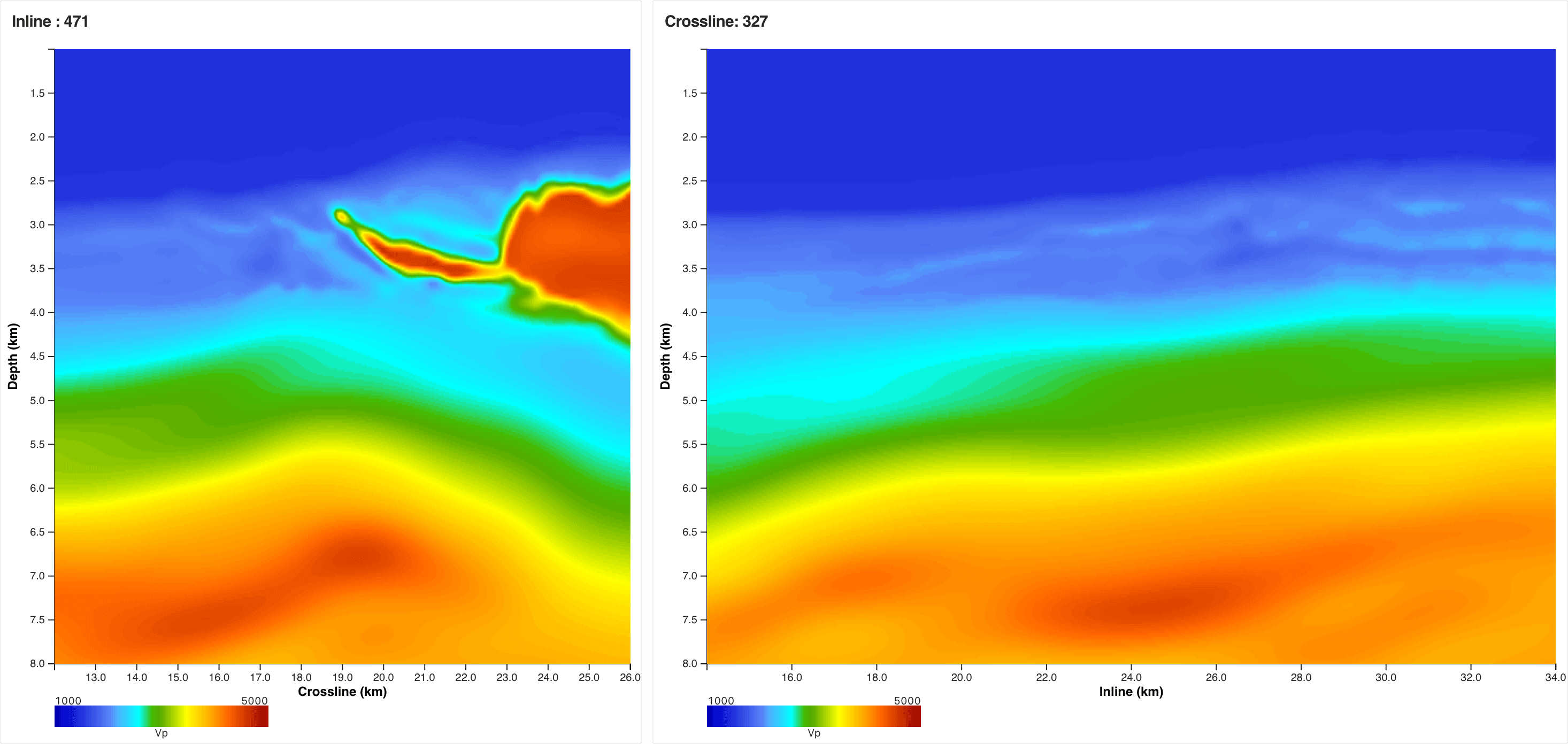
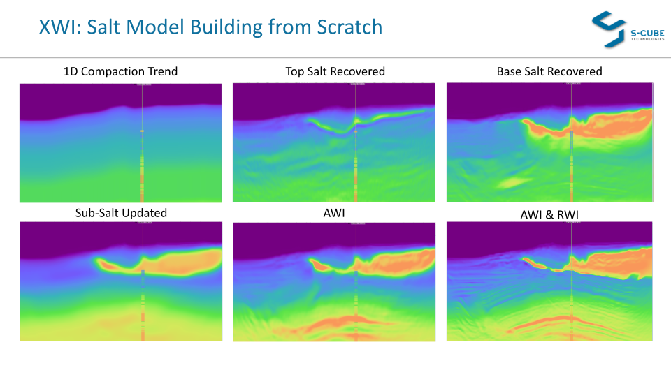
- ▹FWI is normally the last step of a depth-imaging sequence, polishing a model built by years of tomography and salt interpretation. At Alaminos Canyon we are the first to use FWI as the primary model-building tool — the salt is recovered from scratch.
- ▹Adaptive Waveform Inversion (AWI) does the salt work: it conjures the top salt out of a smooth, salt-free start and then dissolves a salt flood into real salt geometry.
- ▹Reflection Waveform Inversion (RWI), guided by the reflectivity, takes over beneath the salt — updating the sub-salt velocity trend where diving waves cannot reach.
- ▹The final stages combine AWI and RWI, sharpening the salt and resolving the deep sediment structure at the same time — every step tracked in velocity and pseudo-reflectivity.
In Breaking Through Complex Salt we told the story of the Alaminos Canyon (ALM) model build. This post steps back and walks the sequence itself: the order in which the salt is recovered from scratch, which tool does which job at each stage, and — since the terms carry the whole story — what AWI, RWI, and reflectivity actually mean.
Recover Salt Model from Scratch
In a conventional depth-imaging project, Full Waveform Inversion arrives at the end of the processing sequence. A velocity model is first assembled over months or years — reflection tomography, top-salt and base-salt picking, salt flooding, scenario testing — and FWI is applied as a final refinement, adding detail to a model that already contains the answer in outline.
On ALM we invert that order. FWI is the primary model-building tool — to our knowledge the first time a complex Gulf of Mexico salt model has been built this way. The starting model contains no salt, no picked horizons, and uses no well data. Everything the panels below show — the salt canopy, its base, the sub-salt sediment trend, the deep reflector package — was put there by waveform inversion acting on the raw field data.
Doing that requires more than a single algorithm. The sequence alternates between two complementary engines — AWI to define the salt, RWI to fix what lies beneath it — with the reflectivity acting as the running readout of both. Before walking the stages, here are the three terms doing the work.
The toolkit, defined
Definition
Adaptive Waveform Inversion(AWI)
Conventional FWI compares predicted and observed seismograms sample-by-sample, which fails — cycle-skips — when the starting model is more than half a wavelength wrong. AWI instead connects the two datasets with matching (Wiener) filters and drives those filters toward a spike at zero lag. Because the filters can absorb arbitrarily large time shifts, AWI remains stable no matter how wrong the starting model is — which is exactly what lets it start from a model with no salt at all and drive the multi-kilometre-per-second updates that salt demands. On ALM, AWI is the engine of the A- and B-stages: it is what defines the salt.
Definition
Reflection Waveform Inversion(RWI)
Transmitted (diving) waves only penetrate so deep — and beneath a salt canopy, hardly at all. RWI extends the update below that limit by using reflected energy instead. It splits the model into a smooth background plus a reflectivity: the reflectivity bounces energy off deep interfaces, and the travel-time errors of those bounced arrivals are converted into long-wavelength updates of the background velocity along the reflection wavepaths. On ALM, RWI takes over from the C-stage onwards: it is what updates the sub-salt velocity trend that diving waves cannot see.
Definition
Reflectivity(pseudo-reflectivity)
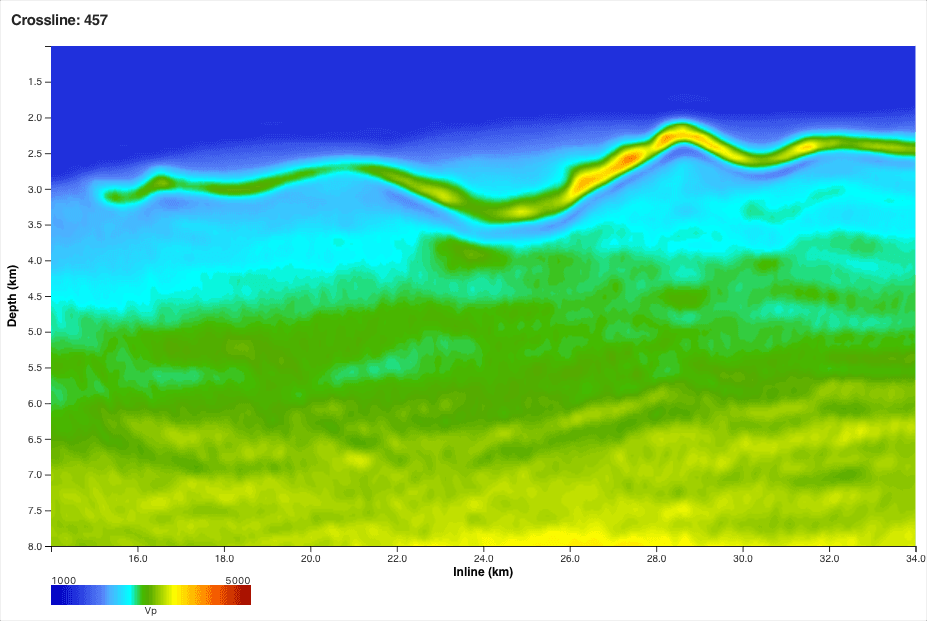
A reflectivity is an image of the model's interfaces — where the velocity changes abruptly, as it does at top salt, base salt, and sediment boundaries. The greyscale panels in this post are a pseudo-reflectivity: the vertical derivative of the velocity model itself. We are not inverting for reflectivity at this stage — the derivative simply lets us read the velocity model the way an interpreter reads a migrated image. Its virtue as a QC is that it is unforgiving: sharp, geologically coherent interfaces only appear in the derivative if the inversion has genuinely put them in the velocities.
How to read the panels
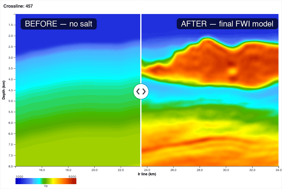
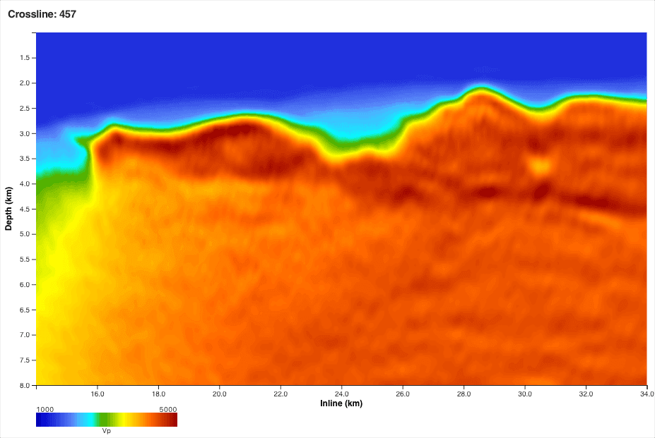
Every figure below is the same slice through the 3D model — crossline 457, displayed from 1 to 8 km depth — shown as a before / after slider at four stages of the sequence. Each stage gets two views: the velocity model (colour, 1000–5000 m/s) showing what the inversion changed, and the pseudo-reflectivity (greyscale) showing whether those changes assemble into geology. The stages are named by their run codes — A008, B026, C042, C112 — and the "before" of each stage is where the previous one left off.
Stage A (A008): AWI finds the salt
The sequence opens from a deliberately naive starting point: a smooth, one-dimensional-looking sediment trend with no salt anywhere in it. Its pseudo-reflectivity is correspondingly empty — a seabed, a few gentle trend contours, and nothing else. AWI is then let loose on the raw data, and because its matching filters cannot cycle-skip, it is free to make the enormous velocity changes the data demands. By the end of the stage, a sinuous, high-velocity ridge has materialised between 2 and 3.5 km depth. That is the top of the salt canopy — not picked, not interpreted, but conjured directly from the waveforms.
 A008 after AWI
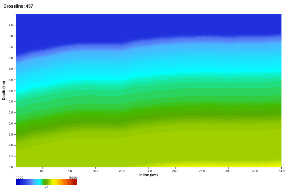 A008 start · no salt
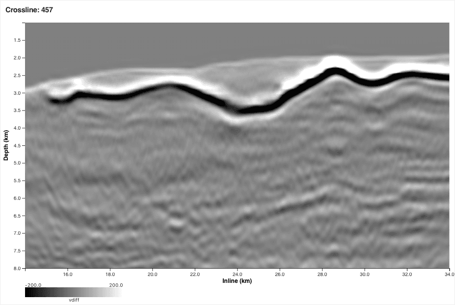 A008 after AWI
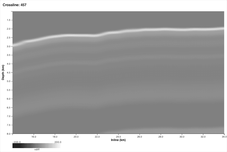 A008 start
Stage B (B026): AWI dissolves the flood
With the top salt established, the model is flooded: everything beneath the canopy is set to salt velocity, the classic way of asking "how deep does the salt really go?" — except that here the flood itself came from constrained AWI rather than from a picked horizon. The B-stage then lets unconstrained AWI attack the flood. Where there is genuine salt, the flood velocity survives; where there is not, AWI pulls the velocity down and the flood begins to dissolve. The flood's uniform mass roughens and differentiates — the texture that appears is the base of salt starting to declare itself.
 B026 after AWI
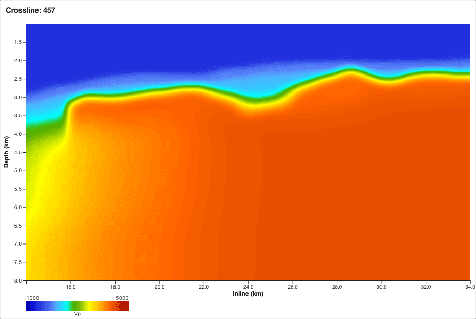 B026 start · flooded
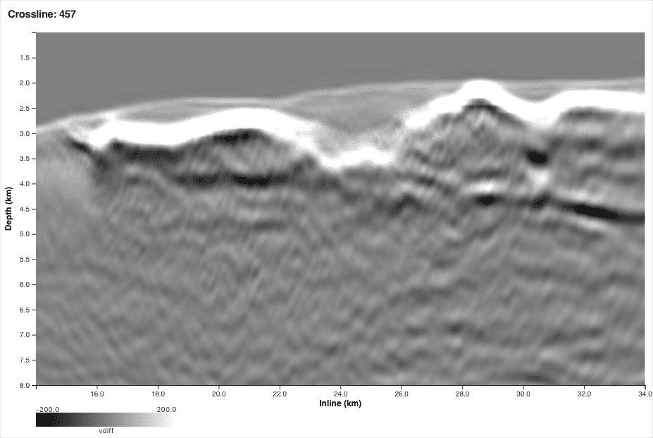 B026 after AWI
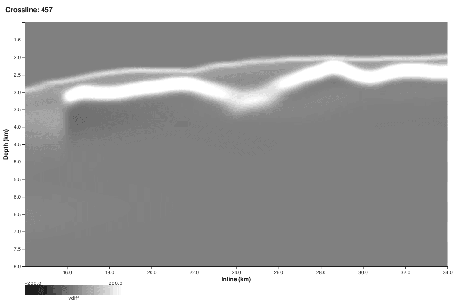 B026 start · flooded
Stage C (C042): RWI corrects the sub-salt trend
By the start of C042 the flood has been fully resolved into a salt body with a top and a base — but everything beneath that base is still the smooth trend the model started with, because diving waves barely penetrate a salt canopy. This is where the toolkit changes hands: RWI, working with the reflectivity, uses the deep reflections themselves to update the sub-salt velocity trend. Below 5 km, the featureless trend develops long-wavelength structure, with velocity highs building near 6.5–7 km. In the pseudo-reflectivity the same update makes the deep section snap into focus — a reflector package appears at 7–7.5 km that simply did not exist in the model before.
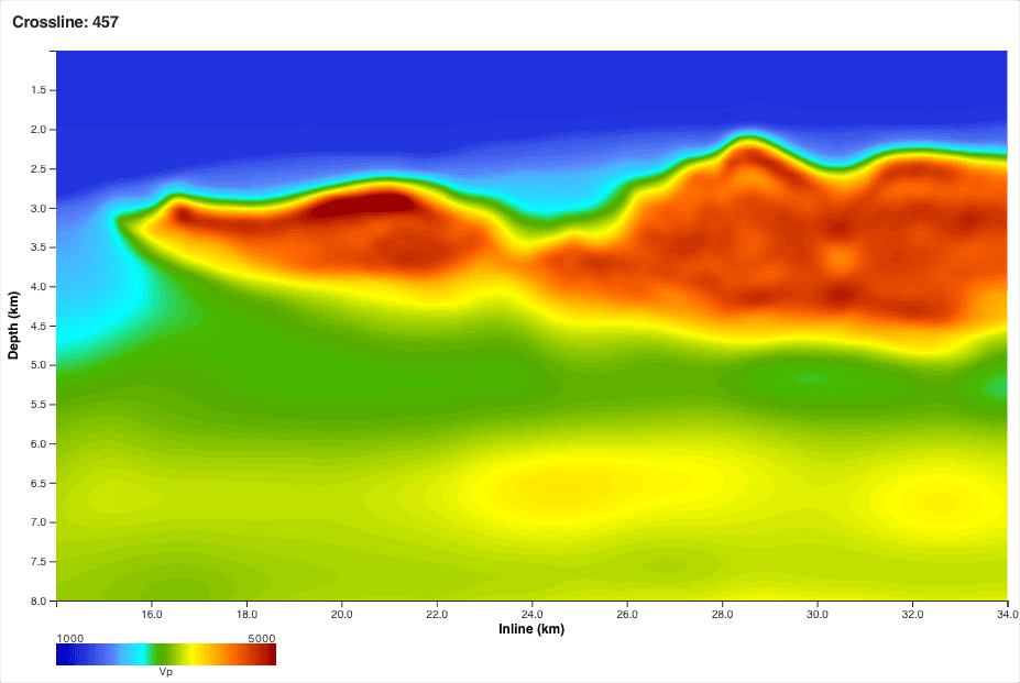 C042 after RWI
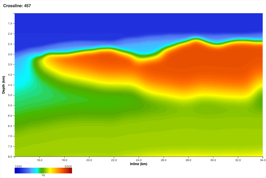 C042 start
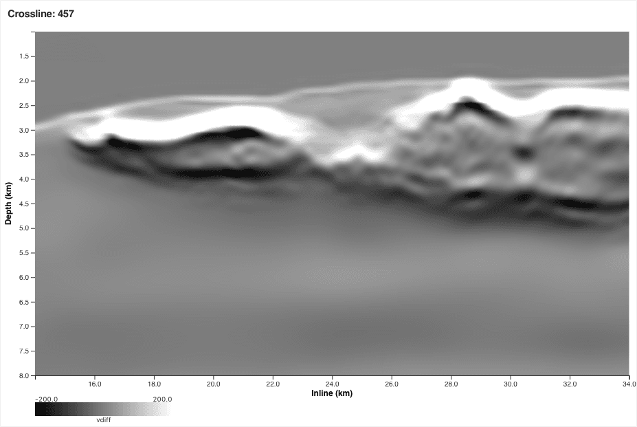 C042 after RWI
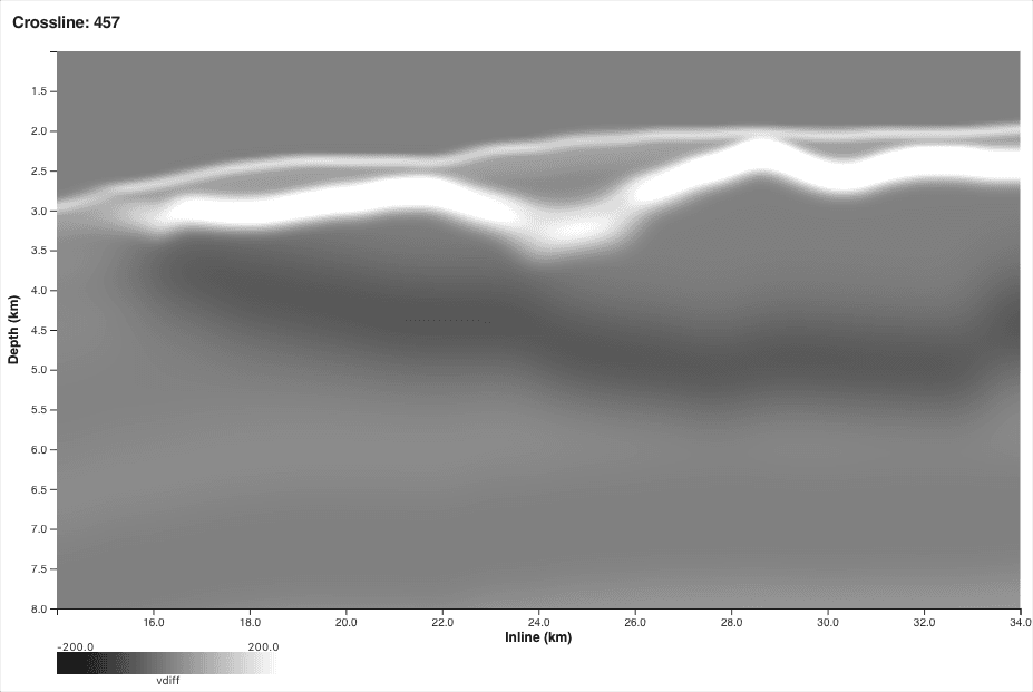 C042 start
Stage C continued (C112): AWI and RWI together
The final stages run AWI and RWI in combination — AWI refining the salt and the shallow section where transmitted energy constrains the model, RWI continuing to keep the deep reflection kinematics honest. The two engines reinforce each other: a better salt body improves the illumination RWI works with, and a better sub-salt trend lets AWI place the salt boundary more precisely. Across stage C112 the model acquires its final character: the salt gains internal texture and crisply defined boundaries, the sub-salt sediments organise into layered packages, and the deep reflector strengthens into a continuous event across the section.
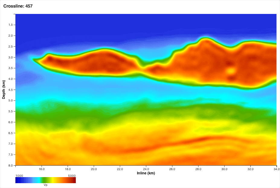 C112 after AWI + RWI
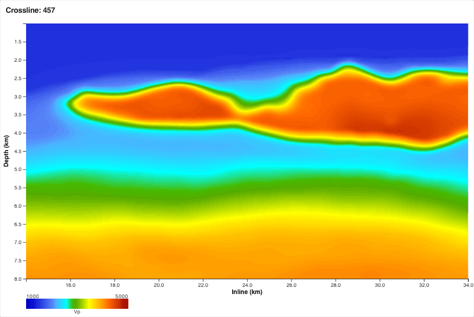 C112 start
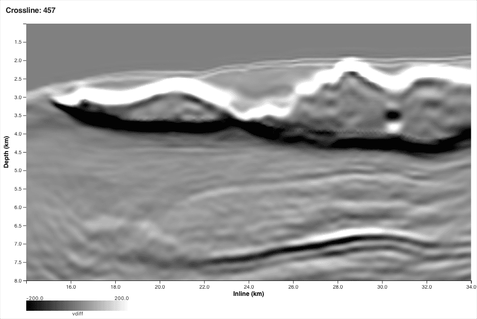 C112 after AWI + RWI
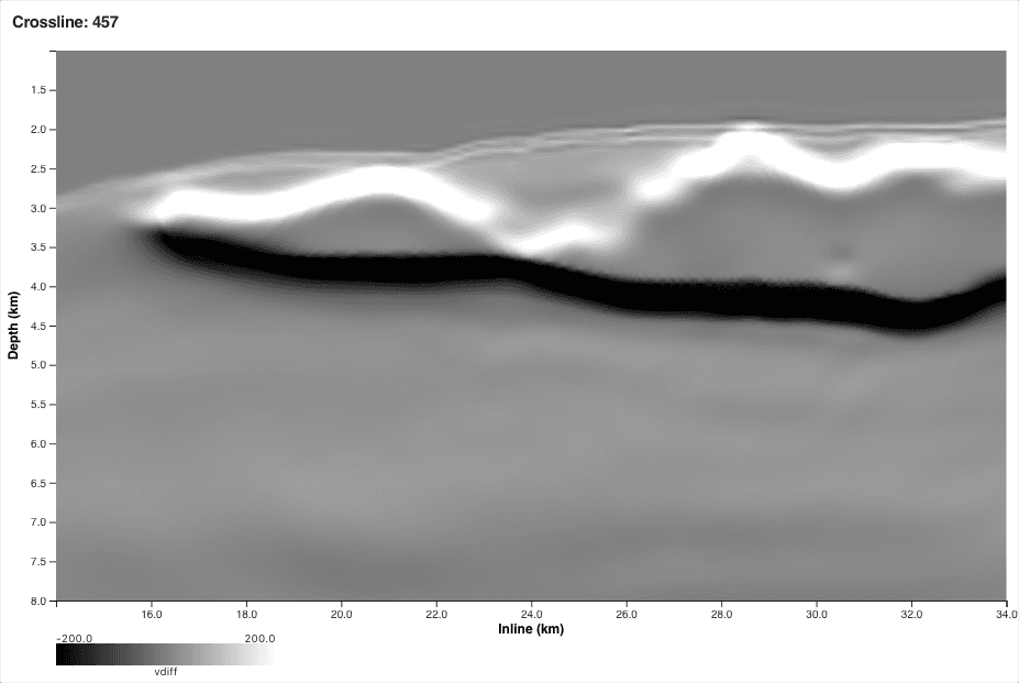 C112 start
The whole sequence in motion
Played end to end, the eight checkpoints above become a single story: a featureless sediment trend grows a salt canopy, floods, dissolves into true salt geometry, gains a corrected sub-salt trend, and finishes as a fully textured model.
Start · no saltThe takeaway
Read the four stages in order and the division of labour is clear. AWI, immune to cycle skipping, does what no conventional FWI can: it starts from nothing and defines the salt — first conjuring the canopy (A008), then dissolving the flood into real geometry (B026). RWI then does what transmitted energy cannot: it carries the update beneath the salt, correcting the sub-salt trend from the reflections themselves (C042). And the combination of the two (C112) delivers a model that is sharp, textured, and geologically coherent from seabed to 8 km — with the pseudo-reflectivity confirming, stage by stage, that every interface was earned from the data. That is what it means to use FWI first, not last.
Could your next model build start with FWI?
Every panel in this post came straight from the live XWI workflow — no picking, no flooding scenarios, no well constraints. If your salt province is stuck in a multi-year model-building cycle, let's talk about running FWI first.
Talk to our teamExplore further
- → Read the full story: Breaking Through Complex Salt
- → The latest progress update: Sharpening Salt, Fixing Sub-Salt
- → Step through the full 15-stage model-building sequence (interactive)
Part of our ongoing work at Alaminos Canyon, Gulf of Mexico, in partnership with Shell. The authors thank Shell for permission to present this work and to use the dataset shown.